Home / Custom Filters / Sine Wave and dv/dt Filters
Sine wave and dv/dt filters for motor drives
Fast switching devices make drives smaller and more efficient, and they also send steep voltage edges down the motor cable. Above a critical cable length, the reflected wave can nearly double the voltage at the motor terminals. A dv/dt filter slows the edges. A sine wave filter removes the switching frequency altogether. We design both, and the inductors that decide how well they work.
Why fast edges damage motors
The motor cable behaves as a transmission line. When the rise time of the drive voltage is short compared with twice the travel time along the cable, the edge reflects at the motor terminals, whose impedance at high frequency is much higher than the cable's. The terminal voltage can then approach twice the DC link voltage, concentrated on the first turns of the winding. Repeated at every switching edge, that stress ages the turn insulation, and the common mode voltage drives currents through the motor bearings.
The critical cable length is roughly the propagation speed times the rise time divided by two. The wave travels at c/√εr, where εr is the relative permittivity of the cable insulation, typically between 100 and 200 m/µs in motor cables. Taking a conservative 100 m/µs, a 200 ns edge gives 10 m, a 50 ns edge 2.5 m and a 20 ns edge 1 m. With SiC devices, almost any motor cable is longer than critical.
Motor standards give guidance on the voltage the winding can take, for example IEC 60034-25 and NEMA MG1 Part 31, and the motor maker's limit is the one that applies.
dv/dt filters: rise time against overshoot
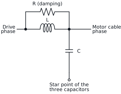
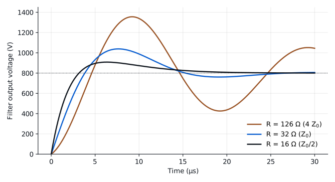
A dv/dt filter is an inductor in series with each phase and a capacitor network at its output, with resistors to damp the resonance. The figure shows the response of an example filter, 100 µH and 100 nF, to an 800 V edge, with the damping resistor across the inductor and the motor not yet connected.
With a damping resistor of four times the characteristic impedance, 126 Ω, the edge slows to about 190 V/µs, but the output overshoots to 169 %. With 32 Ω, equal to the characteristic impedance, the overshoot falls to 130 % and the slope rises to about 215 V/µs. With 16 Ω, the overshoot falls to 114 % and the slope rises to about 280 V/µs. Less overshoot always costs a faster edge and more loss in the resistor. The motor and the cable load the filter and reduce the overshoot in practice, which is why we size the filter with your cable and motor data, not in isolation.
Sine wave filters: removing the switching frequency
A sine wave filter is an LC low pass filter whose resonance sits well below the switching frequency, so that the motor sees an almost sinusoidal voltage. It also removes most of the high frequency stress on the cable and the motor insulation, and it allows longer cables.
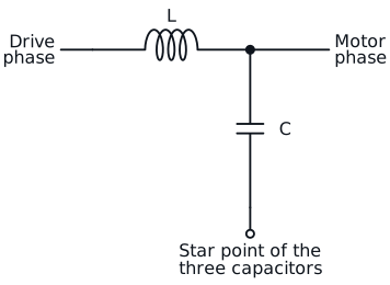
Example: a 15 kW drive at 400 V, with a rated motor current of about 28 A, 8 kHz switching and output frequencies up to 100 Hz. Allowing a 5 % voltage drop across the inductor at 100 Hz gives L = 0.65 mH. Placing the resonance at a quarter of the switching frequency, 2 kHz, gives C = 9.7 µF per phase and about 23 dB of attenuation at 8 kHz.
The inductor carries the full motor current at the output frequency with the switching ripple on top, at the switching frequency. Its core is chosen for low loss at that frequency, and its inductance has to hold at peak current, because a lower inductance moves the resonance up and reduces the attenuation. The resonance must stay away from the output frequencies and from the drive's current control bandwidth.
What to send us
Drive power, DC link voltage, switching frequency and device type, rise time if you know it, output frequency range, cable length and type, motor data or its insulation limit, the filter type you have in mind, and whether you want the inductors only or the complete filter.
Magnetics only or the complete filter, and how we test it: see custom filters.
Straight answers