Home / Custom Filters / LCL Filters
LCL filters for grid-connected inverters
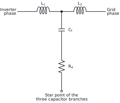
An LCL filter connects a voltage source inverter to the grid through an inverter-side inductor, a shunt capacitor and a grid-side inductor. It attenuates the switching ripple by 60 dB per decade above its resonance, with much less total inductance than a single L filter. The price is a resonance that has to be placed and damped. We design LCL filters and their inductors for PV, battery storage and bidirectional charger inverters.
Sizing an LCL filter: a worked example
Take a 10 kW three-phase inverter on a 400 V, 50 Hz grid, with a 700 V DC link and 20 kHz switching. The rated current is 14.4 A RMS, 20.4 A peak.
- Inverter-side inductor L1. It limits the peak to peak switching ripple, here to 20 % of the rated peak current, 4.1 A. A simulation of the modulated inverter voltage gives L1 = 1.2 mH, with a maximum ripple of 4.0 A peak to peak.
- Filter capacitor Cf. Its reactive power is limited to 5 % of the rated power, so that it does not load the inverter at fundamental frequency. With a base impedance of 16 Ω, that gives 9.95 µF per phase in star.
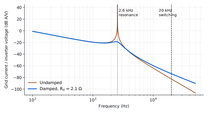
- Grid-side inductor L2. It sets how much of the ripple reaches the grid. To bring the switching harmonic below 0.3 % of the rated peak current, the filter needs about 30 dB of attenuation at 20 kHz between the inverter-side current and the grid current. An undamped filter reaches that with L2 = 0.21 mH.
- Damping. A resistor in series with each capacitor, about one third of the capacitor impedance at resonance, removes the resonant peak. But it also costs attenuation at the switching frequency: with L2 = 0.21 mH and the damping in place, the 30 dB fall to 24 dB. So L2 is sized with the damping included. The result is L2 = 0.58 mH and a damping resistor of 2.1 Ω, which together give the 30 dB at 20 kHz.
- Resonance check. The resonant frequency is 2.6 kHz, between 10 times the grid frequency (500 Hz) and half the switching frequency (10 kHz).
- Losses. The damping resistors dissipate about 3 W at 50 Hz and about 4 W from the switching ripple, about 7 W for the three phases.
Step 4 is the one most often skipped. Sizing the grid-side inductor without the damping, and adding the resistor afterwards, would have left this filter 6 dB short at the switching frequency.
The inductors are where LCL filters go wrong
The two inductors see very different currents, and they should not be designed the same way.
The inverter-side inductor carries the full 50 Hz current with the switching ripple on top. Its core loss is set by the ripple, at the switching frequency, and it changes along the mains period because the ripple does. Powder cores such as sendust or high flux, amorphous and nanocrystalline cut cores are the usual candidates; the right one depends on the total current. Most powder materials lose part of their inductance as the current rises, so the inductance has to be specified at the peak current, not at zero current. A 20 % drop at peak raises the ripple by 25 % and moves the resonance up.
The grid-side inductor carries almost pure 50 Hz current. Its loss is mostly copper loss, and its inductance has to hold at the peak current and at the highest temperature. Because it sets the attenuation reaching the grid, a lower inductance than designed shows up directly as higher harmonic current.
In both, the inductance tolerance moves the resonant frequency. A 10 % change in L1 or L2 moves it by up to about 5 %, which matters when the resonance is close to a control bandwidth or to a grid harmonic.
Passive or active damping
Passive damping with a resistor in series with the capacitor is simple and does not depend on the controller. Its cost is the loss in the resistor, which grows with the switching ripple. Variants with a parallel RC branch reduce that loss. Active damping moves the problem to the control loop, which needs current or capacitor voltage sensing and is sensitive to the grid impedance. In weak grids, where the grid inductance adds to L2 and lowers the resonance, we size the filter so that it stays stable over the range of grid impedance you specify. Often in practice, a combination of passive filter plus additional active damping is the optimal trade-off.
What to send us
Power, grid voltage and frequency, DC link voltage, switching frequency and modulation, the harmonic standard to meet, the range of grid impedance, cooling and ambient temperature, and whether you want the inductors only or the complete filter.
Magnetics only or the complete filter, and how we test it: see custom filters.
Straight answers