Home / Custom Filters / EMI Filters
Custom EMI filters, designed from your emissions scan
An EMI filter attenuates the conducted noise a converter sends back to its supply, in the 150 kHz to 30 MHz band of the CISPR standards. It has two jobs, common mode and differential mode, and each one is limited by something different. We design EMI filters from the measured scan, and supply the chokes alone or the complete filter.
From the scan to the filter: a worked example
Suppose the measured common mode emissions exceed the limit by 44 dB at 150 kHz. With a 6 dB margin, the filter has to give 50 dB there.
A single LC stage gives 40 dB per decade above its corner, so its corner has to sit at 150 kHz × 10^(−50/40), about 8.4 kHz. With two Y capacitors of 4.7 nF, 9.4 nF in common mode, that needs a common mode inductance of about 38 mH.
A two-stage filter gives 80 dB per decade, so each stage can have its corner at about 36 kHz. With the same Y capacitance per stage, that is about 2.1 mH per stage, nearly twenty times less inductance per choke.
The second reason to split the filter is self-resonance. With a winding capacitance of 10 to 40 pF, a 38 mH choke resonates between 130 and 260 kHz, inside the band it is supposed to filter. Two smaller chokes resonate much higher.
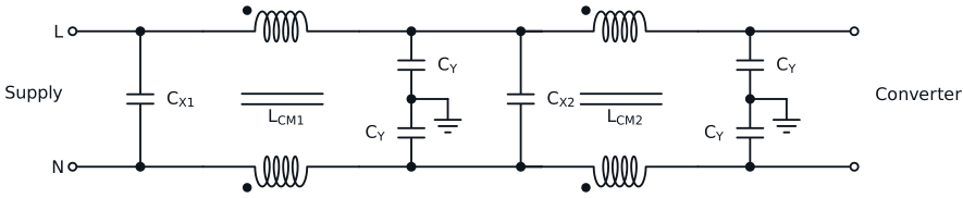
Common mode and differential mode are two different filters
Common mode noise flows through the parasitic capacitance of the switching node and the heatsink to ground, and returns through the earth. It is filtered by a common mode choke and Y capacitors to earth. The Y capacitance is capped by the touch current limit of the safety standard, often to a few nanofarads, and much lower in medical equipment. That is why common mode attenuation usually has to come from inductance.
Differential mode noise flows between the lines. It is filtered by X capacitors and by differential inductance. The leakage inductance of the common mode choke often provides part of it, so we design the choke for a defined leakage as well as for its common mode inductance.
A common mode choke must not saturate with the differential current, and its core material sets where it works. High permeability MnZn ferrite and nanocrystalline give high impedance at the low end of the band. Lower permeability ferrites keep it at the high end. Choosing the material from the frequency of the worst peak in the scan is often more effective than adding turns.
Stability: the filter and the converter
A switching converter with regulated output power behaves, at low frequency, like a negative input resistance of magnitude V²/P. An undamped input filter connected to it can oscillate. The filter output impedance has to stay well below the converter input impedance at every frequency, which usually needs damping at the filter resonance. We check that condition at your lowest input voltage and highest power, where the converter input impedance is lowest.
What to send us
The measured conducted emissions scan, common and differential mode if you have them separated, the standard and class, the supply voltage and current, the Y capacitance your safety standard allows, the converter power and input voltage range, the space available, and whether you want the chokes only or the complete filter.
Looking only for the common mode choke? See our common mode chokes. Magnetics only or the complete filter, and how we test it: see custom filters.
Straight answers